INTRODUCTION TO SHADERS IN MAX/MSP
- See what is a Shader and what you can do with it.
- Know the objects to use in Max/MSP to create a shader.
- See how to code a shader in the Max environment.
- Understand transformations and coordinate spaces in GLSL.
- Know how to communicate with the shader from the Max patch.
Required Level: Since we are going to start from scratch there is no previous knowledge of shaders required for this tutorial, however it is required a minimum level of knowledge about GL objects in Jitter:
you can work with [jit.matrix], [jit.world] and [jit.gl.gridshape].
Basic skills in text programming would be good.
If you don’t know anything about these topics you can take a look at my video introduction at this link.
Introduction
Welcome to my first written tutorial about creating visuals in the software Max/MSP. I would like to start with shaders because it's one of the topics that most intrigue me and also one of the most powerful tools we have in Computer Graphics for creating beautiful visuals.
Let’s now start by seeing what is a shader.
What is a Shader?
A shader is a program that runs on the GPU (the graphic card) of our computer and it’s mostly used to modify the appearance of 3D objects, create light effects for virtual scenes and process images. Shaders perform those task in a very fast and efficient way.
A single shader is actually composed by two programs: a vertex shader and a fragment shader.
There is also another type of program available in Max called geometry shader, but for the moment let's not bother with it.
The vertex shader performs vertex operations on every single vertex one at a time, passing the calculated data to the fragment shader.
The fragment shader then calculates the color for every pixel that represents the shape on the drawing window.

Vertex / Fragment structure.
A fragment is a pixel that belongs to the shape displayed on the window.
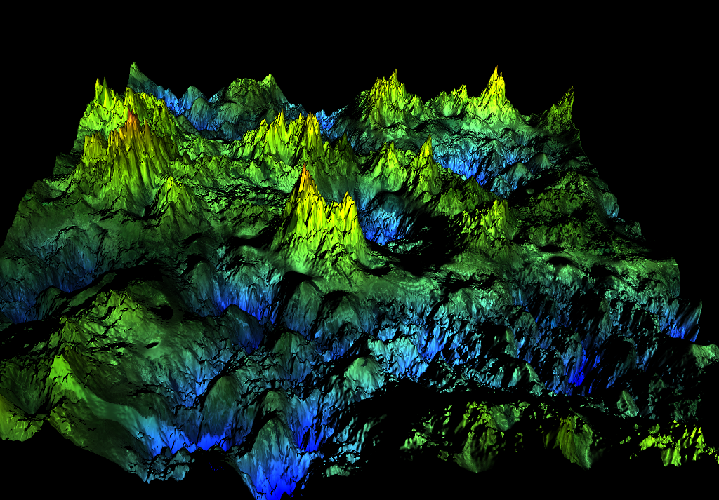
A shader can for example modify the shape of an object by displacing its vertices (vertex shader):
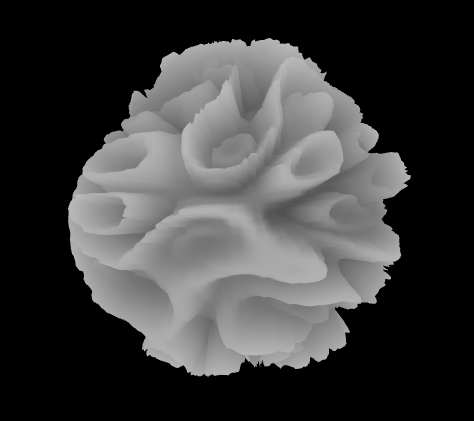
Sphere displaced with noise.

Displacement + color and light.
The vertex and the fragment shaders in fact operate on a single vertex or fragment at a time, working in parallel for all the vertices and the fragments.
For example
If we sum the colors of two images on the CPU, this will have to perform the addition of every single pixel one at a time, and the only parallelism will come from working with a multiple cores CPU.
This is how the addition gets performed by the CPU (not using shaders):
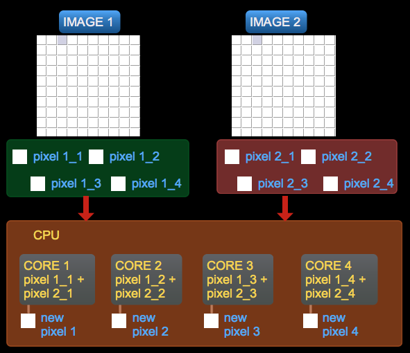
Sum of two images on the CPU.
If we execute the same sum on the GPU, this will assign every pixel to a different core (depending on the number of cores in the graphic card), therefore performing the addition in parallel and much faster.
Addition on the GPU (using shaders):
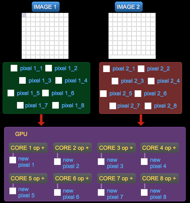
Sum of two images on the GPU.
Let's now see where shaders find place in the computer graphics rasterization process, by introducing the Fixed Function Pipeline.
The Fixed Function Pipeline
When displaying graphics our computer performs a series of operations on the GPU that transform the numerical data provided by our application in 2 dimensional images that can be displayed by our screen. Such operations include vertex transformations, coloring, lighting calculation and texture application. This series of operations is called the Fixed Function Pipeline.
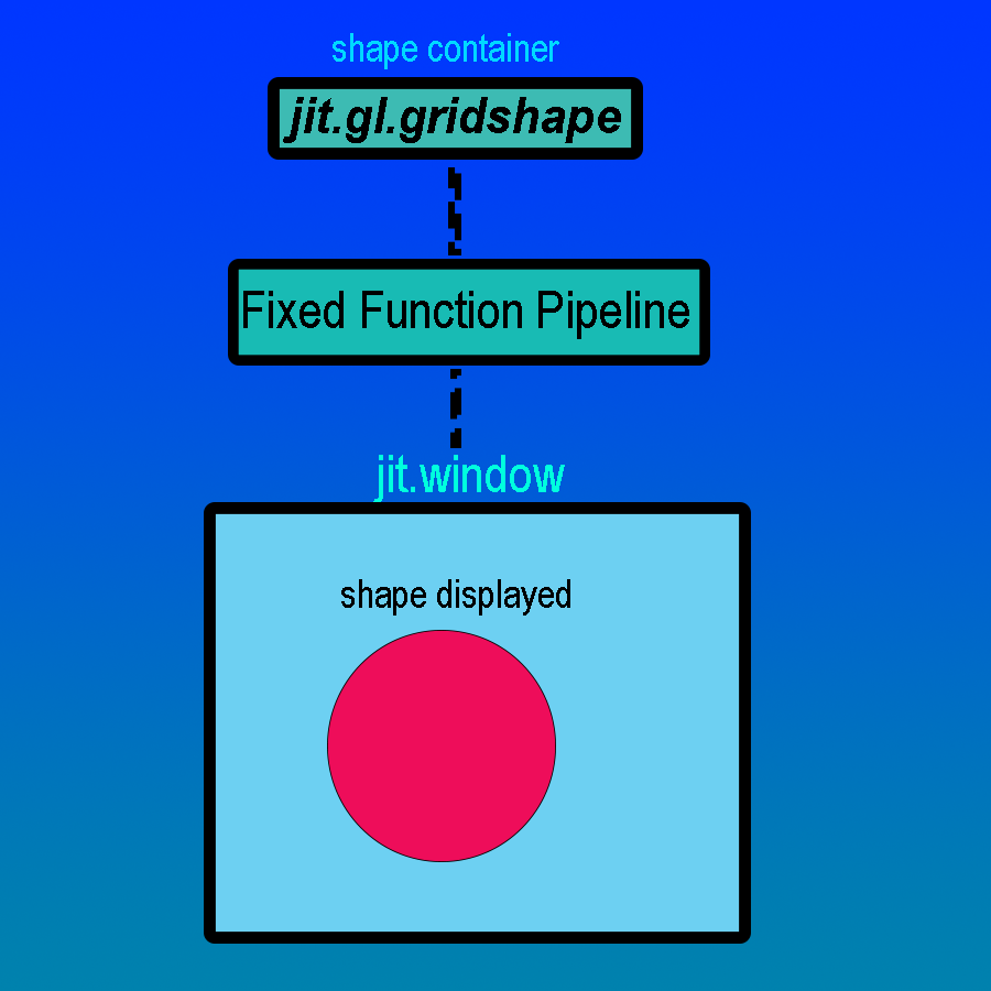
Default Processing.

Using a Shader.
Shaders in Max
So let's now see how we can write and use shaders in Max/MSP. There are two ways:
1. Using the [jit.gl.shader] object we can attach a shader to GL objects that contain 3D shapes, such as [jit.gl.gridshape], [jit.gl.mesh], [jit.gl.plato] and so on. In this way we can modify the vertices of the shape and the color of the pixels that will represent it on the screen.
2. By feeding shaders with textures and use them as processing kernels for images. In this case we use [jit.gl.slab] and [jit.gl.pix].
Let's get Started
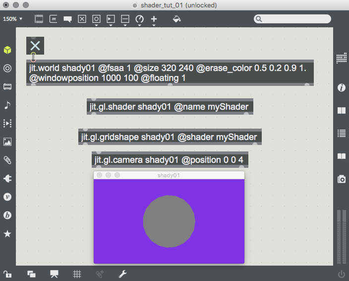
First of all in a new patch let's create four objects: [jit.world], [toggle], [jit.gl.gridshape] and [jit.gl.shader]. Let's name the GL context "shady01" and connect the toggle to [jit.world].
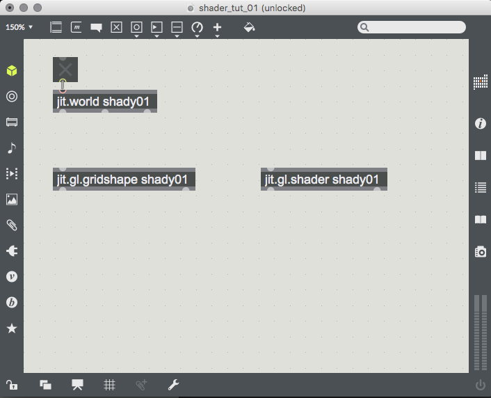
Our new patch.
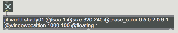
[jit.world] with attributes.
- We can activate the anti-aliasing with the @fsaa 1 attribute in order to have a smoother image without jagged edges.
- We can choose the size of the window in pixels using the @size attribute.
- Then we can set the background color for our window using the @erase_color attribute and some values in between 0 and 1 (the values in my [jit.world] will give you a nice purple).
- If you want you can also set the default window position in your screen using @windowposition.
- And finally tell the image to never disappear behind the patch with the @floating 1 attribute.
Note that none of these attributes is strictly necessary, but I find that especially the @fsaa 1 is always a good boost for our visuals.
Now our next step will be to attach the shader contained inside the [jit.gl.shader] object to the [jit.gl.gridshape] object.
In order to do that we need to give a name to the [jit.gl.shader] using its @name attribute and refer to this name in the argument of the @shader attribute of [jit.gl.gridshape].
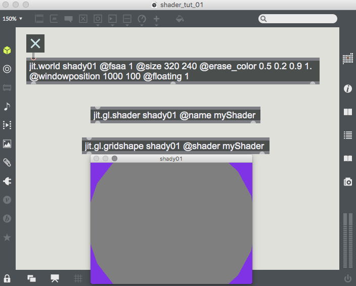
[jit.world] with attributes.
Also the sphere appears quite big, which means that it's too near to our virtual camera. To solve this problem let's take control of the camera and move it a bit further away along the Z axis. We do this by creating a [jit.gl.camera] and set its @position attribute to [0 0 4].
[jit.gl.camera] moved along the Z axis.
Max utilizes a special file type for describing shaders called jxs. It's a sort of xml tree structure that allows [jit.gl.shader] and [jit.gl.slab] to load and configure the shader program.
If you never wrote a line of text code in your life don't get scared. It's really not difficult to understand the basic principles, and once you have those, to become a master it's just a matter of practice.
Just remember to write the syntax exactly how it is presented (computers are quite exacting on that point).
So let's create a .jxs file in which to write our shader. We can do that by double clicking on the [jit.gl.shader] object and save the current empty file. We will be asked to create a new file and choose a name and location for it. I called mine myFirstShader.jxs but you can choose the name that you prefer as long as you add the .jxs appendix to it.
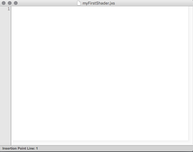
New empty .jxs file.

@file attribute of [jit.gl.shader].
Writing the Shader
XML Skeleton
Now we have to write the skeleton for our shader, which consists on a series of xml tags.
The first thing we need is to define a name tag for this shader, so let's write the following line inside the shader editor.
<jittershader name = "myFirstShader">
I used the same name as our file but could have chosen a different one. As you can see we don't close this tag with a </jittershader> closing tag, since this is the outer layer in which our shader program is contained and will stay opened until the end of the file.
Then we can add a description of what this shader does (optional).
<description> That is my first shader </description>
Note that this line is not necessary, and it's just there to inform the reader of the shader on what is its function. After that we have to specify which language we are using for writing our shader and its version. In fact there are several languages for writing shaders such as HLSL, OSL and others.
We are going to use GLSL version 1.2, which although is quite old is the most utilized in the Max world (and very utilized also outside of Max).
GLSL is an acronym for OpenGL Shading Language, and since OpenGL is the rendering API utilized by Max makes sense to use the shading language
created for it.
To specify the language and the version we have to add this line:
<language name = "glsl" version = "1.2">
We don't close this tag either. We are almost finished with the skeleton and are almost ready to write real GLSL code, but before we have to specify which shader we are going to write.
As we saw in the beginning of this tutorial, there are mainly two kinds of shaders: vertex and fragment.
The vertex shader passes its output to the fragment shader, so it's the first stage of the processing chain.
To start writing the vertex shader we have to add these two lines:
<program name = "vp" type = "vertex">
<![CDATA[
The second line means that what we are going to write after the square bracket must not be interpreted as xml code.<![CDATA[
Now our code should look like that:
<jittershader name = "myFirstShader">
<description> That is my first shader </description>
<language name = "glsl" version = "1.2">
<program name = "vp" type = "vertex">
<![CDATA[
And we are ready for writing our first vertex shader!<description> That is my first shader </description>
<language name = "glsl" version = "1.2">
<program name = "vp" type = "vertex">
<![CDATA[
The Vertex Shader
The final purpose of the vertex shader is to assign the current vertex value to a built-in variable called gl_Position inside a function main. A built-in variable in GLSL is a variable that is used by the fixed function pipeline as input or output, passing data between our application (the Max patch), the vertex shader and the fragment shader.
A built-in variable is different for every kernel (every shader program that runs on the GPU on a different core), so for every vertex of the shape or for every fragment.
A built-in variable is different for every kernel (every shader program that runs on the GPU on a different core), so for every vertex of the shape or for every fragment.
So first of all we have to write this main function:
<![CDATA[
The main function in the shader code gets called automatically every new frame. void main() {
}From this function as we said we have to set the the value of the built-in variable gl_Position, which is the position of the vertex being processed on the kernel after being transformed from object space to clip space.
The built-in variable gl_Position is read by the fixed function pipeline to know where the vertices of the shape are positioned in the 3D world and where they will be when projected on the two-dimensional screen.
So it's an output variable that we have to fill in the vertex shader.
The fastest way to apply those transformations and create a pass-through vertex shader in GLSL 1.2 is this:
<![CDATA[
Now our vertex shader will simply pass the vertices from the shape to which the shader is attached unaltered.void main() {
gl_Position = ftransform();
}
To conclude the shader program we have to close the <![CDATA[ and close the program tag.
Our code until now looks like this:
<jittershader name = "myFirstShader">
<description> That is my first shader </description>
<language name = "glsl" version = "1.2">
<program name = "vp" type = "vertex">
<![CDATA[
The jxs file is not complete yet, so will still give you errors if you try to activate the [jit.world] rendering. Have no fear, everything will be working fine by the end of this tutorial.
<description> That is my first shader </description>
<language name = "glsl" version = "1.2">
<program name = "vp" type = "vertex">
<![CDATA[
void main() {

    gl_Position = ftransform();
  }
]]>
</program>
Coordinate Spaces and Transformations
Let's stop a moment with the shader code and see what we are talking about when we mention object space, clip space and transformations.
As we mentioned before, when using a shader we are overriding some functions of the fixed function pipeline, and so we have to write them ourselves.
One of these functions is to transform the object from object space into clip space. In order to do that the vertex shader must take the vertices of the shape in object space from the input built-in variable gl_Vertex and multiply this vector for some matrices.
In GLSL we can work with vectors just like in gen. A vertex of a shape is nothing but a 3 components vector (x,y,z) so it can be assigned in GLSL to a vec3 type.
Let's note however, that in GLSL the built-in variable gl_Vertex contains a 4 components vector, where the fourth component is called 'w' and it's used for perspective transformations. Most of the time we won't bother with this fourth component.
Let's note however, that in GLSL the built-in variable gl_Vertex contains a 4 components vector, where the fourth component is called 'w' and it's used for perspective transformations. Most of the time we won't bother with this fourth component.
When we say that we have to multiply the vertex value for some matrices, we are talking about built-in transformation matrices. GLSL in fact, provides us with a matrix for every coordinate space that we may be interested on working in.
To transform a vector means that we are going to change its values by means of matrix multiplication. For example when we scale our 3D object in the Max patch, we are applying a scaling matrix, same thing when we translate it by changing its position or when we rotate it.
Let's note that these matrices we are talking about have nothing to do with Jitter matrices.
Let's note that these matrices we are talking about have nothing to do with Jitter matrices.
So let's now take a look at these coordinate spaces and to the built-in matrices needed to perform the relative transformations.
Object Space
When we create a 3D object such as [jit.gl.gridshape] or [jit.gl.plato], the vertices of the shape are defined relatively to its center.
This doesn't happen only in Max but in every other graphic program that works with OpenGL.

[jit.gl.plato] cube.
We can explicitly see that if we observe the X,Y,Z planes of the matrix that contains a cube in the [jit.gl.gridshape] object.
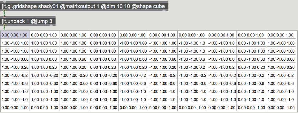
X,Y,Z planes of a [jit.gl.gridshape] cube.
This coordinate space with the zero point in the center of the shape is called the object space or model space, and contains the values that we can access from the built-in input variable gl_Vertex.
World Space
The rendering process however needs to know where this object lies in the world space, which is the coordinate space relative to the center of the world.

The object in world space.
In order to know how the object is positioned in the space we have to multiply the built-in matrix variable gl_ModelMatrix for the value of gl_Vertex.
In the code it would look like that:
gl_Position = gl_ModelMatrix * gl_Vertex;
Eye Space
The eye space is the coordinate space relative to the camera position. It means that the camera is now taken as the center of the world and so its position is (0,0,0). Everything else is translated according to this coordinate space.

The object in eye space or camera space.
To transform the object position into eye space we have to multiply the vertex value for the model matrix and then for the view matrix. As we said before there is no model matrix itself in GLSL because this is always linked with the view matrix. The built-in resulting matrix variable is gl_ModelViewMatrix.
Getting the vertex position in eye space in the code looks like that:
gl_Position = gl_ModelViewMatrix * gl_Vertex;
Note that matrix/vector multiplication is not commutative. This means that we have to write the matrix name first and then the vector name.
For example:
For example:
gl_Position = gl_Vertex * gl_ModelViewMatrixgl_Position = gl_ModelViewMatrix * gl_VertexLet's now take a look at the last coordinate space and relative transformation.
The Clip Space
The clip coordinate space is represented in the shape of a frustum (a truncated pyramid). Is it called clip space because it clips out all the vertices that are too close (closer than the near plane), too far (farther than the far plane) or outside of the camera viewing angle. So everything that is outside of this imaginary frustum.
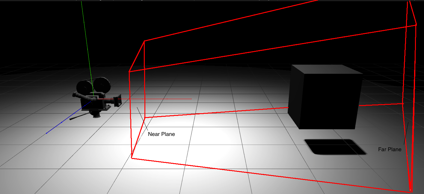
The view frustum, also called clip space.
If we set the attribute @ortho in [jit.world] to a value different from zero we will not have a perspective view but a flat orthogonal view.
Going from vertex position to clip space in the code looks like this:
gl_Position = gl_ModelViewProjectionMatrix * gl_Vertex;
The Fragment Shader
Let's get back to the code! It's time to write the second and last shader that compose our shader program: the fragment shader.
The final purpose of the fragment shader is to assign a vec4 type variable to the built-in output variable gl_FragColor inside a function main. This variable represents the color that the currently processed pixel of the shape will have.
Before we can write our fragment shader we have to specify which type of shader we are going to write as we did before for the vertex shader:
<program name = "fp" type = "fragment">
The name changed to "fp" and the type to "fragment".Now we can open the <
Shape rendered with the shader.
Change the Color
Let's experiment a bit by changing the color values inside the vec4 that gets assigned to the gl_FragColor variable. You can try all the combinations that you want for the red, green and blue channel.
The alpha value will not have any effect because the @blend_enable attribute in our [jit.gl.gridshape] is by default set to 0.
So not enabled.
The range in which to operate is from 0.0 to 1.0. It is important that this numbers get written with the floating point syntax, otherwise your shader could not run on some machines.
This example:
void main() {
gl_FragColor = vec4(0.3, 0.7, 1.0, 1.0);
}

Light blue color assigned through the fragment shader.
Uniforms
Let's say that we want to change the color of the shape dynamically from our Max patch. GLSL offers us a way to do that called uniforms.
Uniforms are a special kind of variable that can be changed from the mother application (in our case Max) once per frame and are the same for every kernel (core processing our shader code), that's why they are called "uniforms".
Built-in variables and uniform differ because the firsts contain values assigned by the fixed pipeline and are different for every vertex or fragment.
Uniforms contain values assigned by the user and are the same for every kernel.
To declare a uniform variable in our shader we have to add a param tag to the xml structure. This line goes after the description tag and before the language tag:
<jittershader name = "myFirstShader">
<description> That is my first shader </description>
<param name = "color" type = "vec3" default = "1.0 1.0 1.0" />
<language name = "glsl" version = "1.2">
<program name = "vp" type = "vertex">
Adding this line we are declaring that we want to pass a value named "color" of type vec3 (so containing 3 floating point numbers) and that its default values are the numbers 1.0, 1.0, 1.0, so a white color. We will use this variable in the fragment
shader to change the color of our sphere.<description> That is my first shader </description>
<param name = "color" type = "vec3" default = "1.0 1.0 1.0" />
<language name = "glsl" version = "1.2">
<program name = "vp" type = "vertex">
Before we can do that, however, we have to add another tag, bind, after the language tag and before the program tag:
<jittershader name = "myFirstShader">
<description> That is my first shader </description>
<param name = "color" type = "vec3" default = "1.0 1.0 1.0" />
<language name = "glsl" version = "1.2">
<bind param = "color" program = "fp" />
<program name = "vp" type = "vertex">
With the bind tag we bind the parameter we just declared to the shader type we want to use that parameter with. In this case the fragment shader. <description> That is my first shader </description>
<param name = "color" type = "vec3" default = "1.0 1.0 1.0" />
<language name = "glsl" version = "1.2">
<bind param = "color" program = "fp" />
<program name = "vp" type = "vertex">
We can have multiple parameters for multiple shaders types adding multiple declarations and bindings.
Adding the Uniform to the Shader
Let's modify the fragment shader in order to include the new uniform variable:
<![CDATA[
As you can see to add the uniform to the shader we have to first declare that it's a uniform using the uniform keyword, and then we can write the type and the name
of the variable. uniform vec3 color;
void main() {
gl_FragColor = vec4(0.3, 0.7, 1.0, 1.0);
}
Since it's a variable that's being passed from the outside, we don't need and can't initialize it with a default value inside the shader. The inizialization was done when we wrote the param tag.
To actually utilize the variable inside the shader we can replace the first 3 values of the vec4 with the color variable. GLSL is smart enough to recognize that a 3 component vector plus a single float value form a vec4.
<![CDATA[
uniform vec3 color;
void main() {
gl_FragColor = vec4(color, 1.0);
}
Before moving to the Max side let's recap and see our code in its completeness:
<jittershader name = "myFirstShader">
<description> That is my first shader </description>
<param name = "color" type = "vec3" default = "1.0 1.0 1.0" />
<language name = "glsl" version = "1.2">
<bind param = "color" program = "fp" />
<program name = "vp" type = "vertex">
<![CDATA[
</program>
<program name = "fp" type = "fragment">
<![CDATA[
</program>
</language>
</jittershader>
Control that you have the same exact code, otherwise the compiler will give you errors.<description> That is my first shader </description>
<param name = "color" type = "vec3" default = "1.0 1.0 1.0" />
<language name = "glsl" version = "1.2">
<bind param = "color" program = "fp" />
<program name = "vp" type = "vertex">
<![CDATA[
void main() {

  gl_Position = ftransform();
}
</program>
<program name = "fp" type = "fragment">
<![CDATA[
uniform vec3 color;

  void main() {

    gl_FragColor = vec4(color, 1.0);
  }
</program>
</language>
</jittershader>
The Patch
And finally, we see how to modify the color from our patch using floating point number boxes. All we have to do is to create a [pak] object with the message "param" followed by the name of our parameter ("color" in our case) followed by as many numbers as our parameter requires (3 floats in our case), and connect it to the [jit.gl.shader] object.
The patch looks like that:
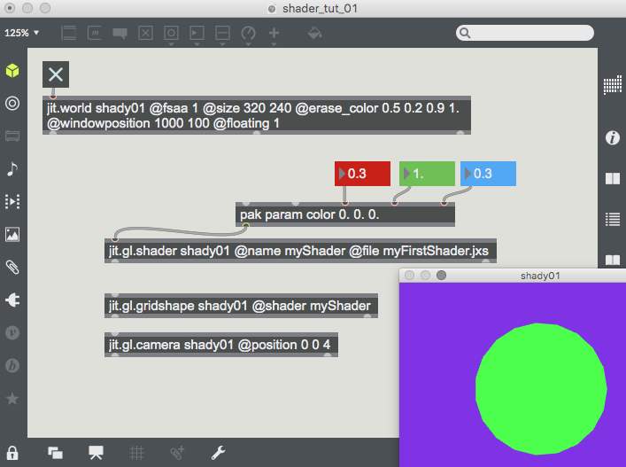
Passing the color parameter to the shader.
Conclusion
That was it for this first introductive tutorial about shaders. By now we didn't achieve anything new that we couldn't have done modifying standard [jit.gl.gridshape] attributes, but as we move forward we will start to see the many possibilities that the world of shaders offers us in terms of graphical effects.
Patreon
Writing this tutorial was a pleasure, but it required quite some time. I couldn't do that if it wasn't for the Patreon friends that support me.
You can support me with a small donation becoming a Patron at this link:
Amazing Max Stuff Patreon.
This will also give you access to all my Patron-only patches.
Donation
If you don't want to create a Patreon account you can also send me a one-time donation:
Thank you guys, this helps me so much!
For all the updates on tutorials or patch sharing follow my facebook page: Amazing Max Stuff FB.